A few weeks ago, while I was reorganizing my workspace I found a 10 meter reel of NeoPixels.
Originally I wanted to put them behind a Ikea Kallax shelf where I put random junk, but since I’m working from home a lot lately it seemed a better idea to put them behind my screen!
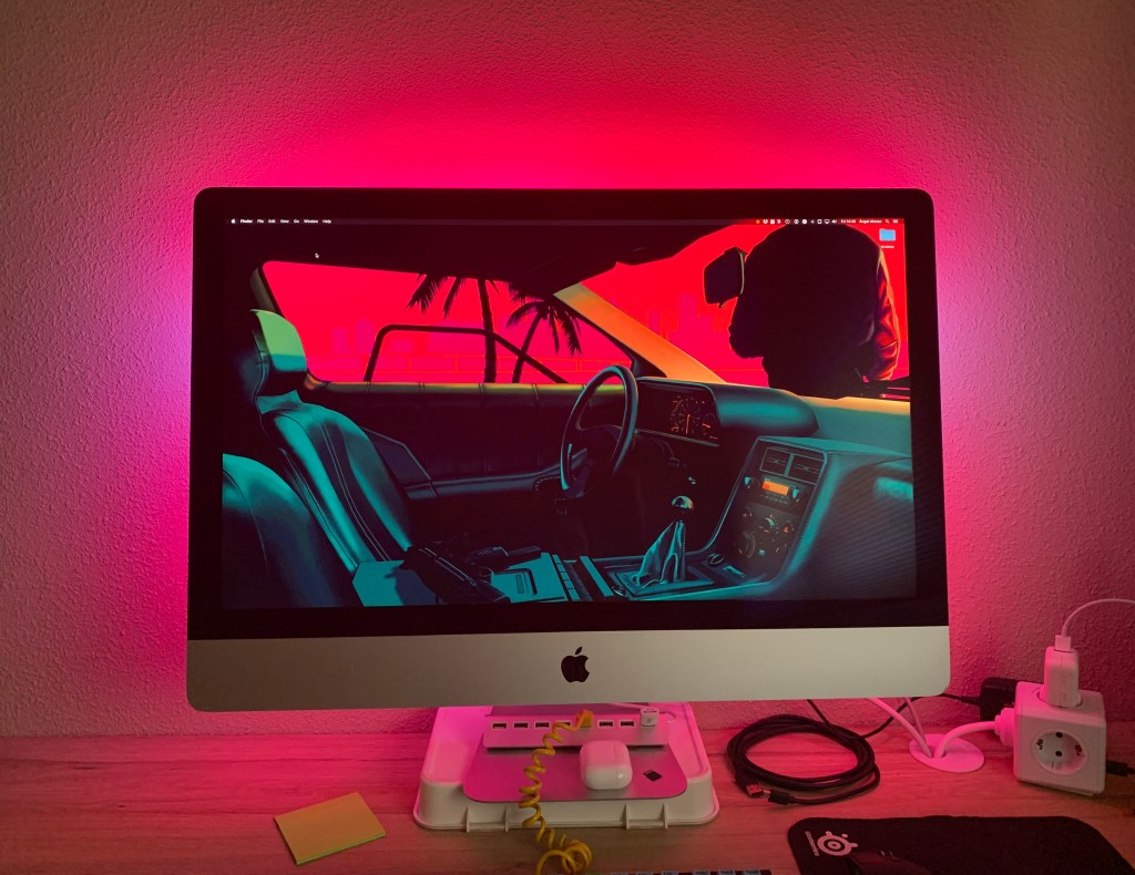
You probably now “bias lighting” as “Ambilight“, which is the commercial name Philips uses on their TVs. It consists on placing RGB LED strips along the edges of a screen and illuminating them depending on the colors of the edges of the image.
The system has two working pieces: a client that captures screen contents and calculates the colors for each LED and a server that receives that information and actually turns each LED to the given color.
Hardware
I like to start project on the hardware side, and then figure out the software. This sometimes bites me in the ass at a later time, but where’s the fun otherwise?
To craft this project you’ll need a few things. You don’t have to use actual NeoPixels, any WS2812 RGB LEDs will do. You can also use any microcontroller that supports FastLED and can be programmed using the Arduino IDE toolchain.
Material list
- RGB LED strip with integrated controller (WS2812)
- Microcontroller (Arduino, ESP8266/ESP32)
- Multi-core cable (26 AWG)
- 1000uF capacitor
- 3A 5V power supply
- Double sided tape
I used an ESP32 I had lying around and I’m not sure if my LEDs are NeoPixels or random WS2812 from AliExpress, but they work.
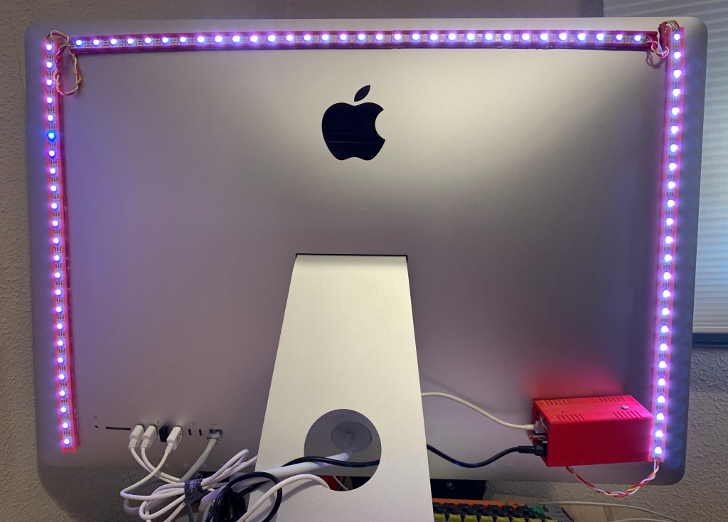
The first thing you need to know is how many pixels are you going to wire in each side. Write this down, since you’ll need to know this number later on when configuring the client app.
If you check out the previous image you’ll see that the LEDs aren’t taped directly to the screen. Since the 2017 iMac has a curved back I designed a “holder” to angle the LEDs parallel (or almost parallel) to the wall. You probably don’t need this, but it’s available on Thingiverse.
I used 32 pixels on top and 24 on each side. You can also add them to the bottom of the screen, but I choose not to to avoid complicating the wiring.

The wiring is fairly simple. You need to place the capacitor between the 5V/3A power supply and the first LED on the first strip. Ground and VCC for the LED strip goes directly to this power supply.
Connect the DIN of the LED strip to any GPIO on the microcontroller and make a note of the pin number, you’ll need that later on.
Ground together the external power supply and the microcontroller and you’re good to go.
The microcontroller will get it’s power from the computer’s USB port and also communicate with the client application with that same USB cable.
Server software
We’ll use two pieces of software to make this work. The first is the server that will run on the microcontroller. In my case, since I’m using Prismatik, it needs to support the Adalight protocol
I can’t figure out where did I get the code I’m using. I’m sorry for not crediting the person who wrote it. If you’re reading this, do let me know!
Click on “expand source” to copy the source code for the microcontroller. You’ll need to edit the NUM_LEDS variable to reflect the total number of LEDs your strip has.
You may also want to edit the PIN variable to match the pin you wired your strip to.
//////////
//
// Arduino interface for the use of ws2812 operated LEDs
// Uses Adalight protocol and is compatible with Boblight, Prismatik etc
// "Magic Word" for synchronisation is 'Ada' followed by LED High, Low and Checksum
//
#include <FastLED.h>

///// User definitions /////

// Define the number of LEDs
#define NUM_LEDS 80

// Define SPI Pin
#define PIN 2

// Baudrate, higher rate allows faster refresh rate and more LEDs (defined in /etc/boblight.conf)
#define serialRate 115200

// Adalight sends a "Magic Word" (defined in /etc/boblight.conf) before sending the pixel data
uint8_t prefix[] = {'A', 'd', 'a'}, hi, lo, chk, i;

// initialise LED-array
CRGB leds[NUM_LEDS];

void setup()
{

  FastLED.addLeds<WS2812, PIN, GRB>(leds, NUM_LEDS);

  // initial RGB flash
  LEDS.showColor(CRGB(255, 0, 0));
  delay(500);
  LEDS.showColor(CRGB(0, 255, 0));
  delay(500);
  LEDS.showColor(CRGB(0, 0, 255));
  delay(500);
  LEDS.showColor(CRGB(0, 0, 0));

  Serial.begin(serialRate);
  Serial.print("Ada\n"); // Send "Magic Word" string to host

}

void loop() {
  // wait for first byte of Magic Word
  for(i = 0; i < sizeof prefix; ++i) {
    waitLoop: while (!Serial.available()) ;;
    // Check next byte in Magic Word
    if(prefix[i] == Serial.read()) continue;
    // otherwise, start over
    i = 0;
    goto waitLoop;
  }

  // Hi, Lo, Checksum

  while (!Serial.available()) ;;
  hi=Serial.read();
  while (!Serial.available()) ;;
  lo=Serial.read();
  while (!Serial.available()) ;;
  chk=Serial.read();

  // if checksum does not match go back to wait
  if (chk != (hi ^ lo ^ 0x55))
  {
    i=0;
    goto waitLoop;
  }

  memset(leds, 0, NUM_LEDS * sizeof(struct CRGB));
  // read the transmission data and set LED values
  for (uint8_t i = 0; i < NUM_LEDS; i++) {
    byte r, g, b;
    while(!Serial.available());
    r = Serial.read();
    while(!Serial.available());
    g = Serial.read();
    while(!Serial.available());
    b = Serial.read();
    leds[i].r = r;
    leds[i].g = g;
    leds[i].b = b;
  }
  // shows new values
 FastLED.show();
}
Use the Arduino IDE to compile and burn this code into your microcontroller. You’ll probably need to install the latest FastLED library for it to work.
If this worked you’ll see a color flash sequence when powering the microcontroller and the LEDs.
With this done we’re ready to install and configure the client and make some LEDs light up!
Client software
I’ve tried a lot of client applications, but the best I found that works fast on macOS is Prismatik. I’m using psieg’s fork, release 5.11.2.22.
On first run the configuration wizard will try to detect a Lightpack (a commercial solution to do bias lighting) and fail, letting you configure another device.
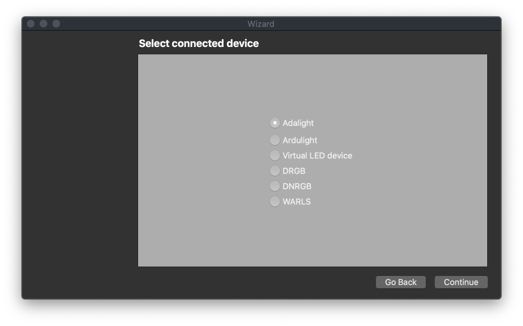
On the device selection check “Adalight”, and continue. Then you’ll need to select the serial port where the microcontroller is connected, in my case is /dev/tty.SLAB_USBtoUART, but this will vary depending on the setup. Leave everything else as is.
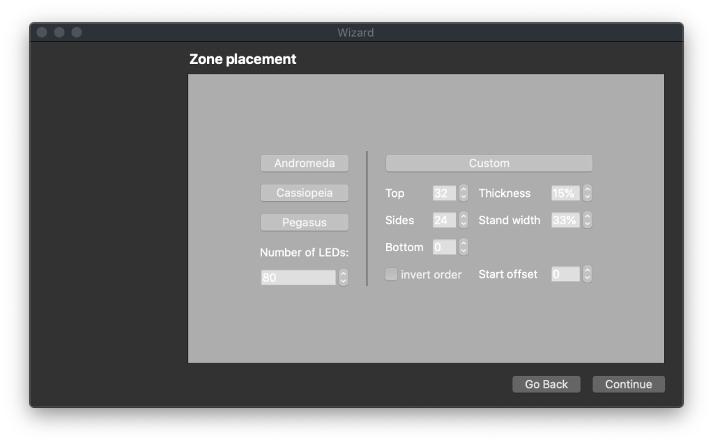
Next up is the Zone Placement. This maps the corners of your screen to each led. Fill out the total number of LEDs, how many of them are on top and on the sides. You can also change the thickness and width of the capture zone, this will affect how much of screen color is averaged to set the LED color.
Once you’re finished you’ll start to see the color change with the screen contents, but we’re not done yet!
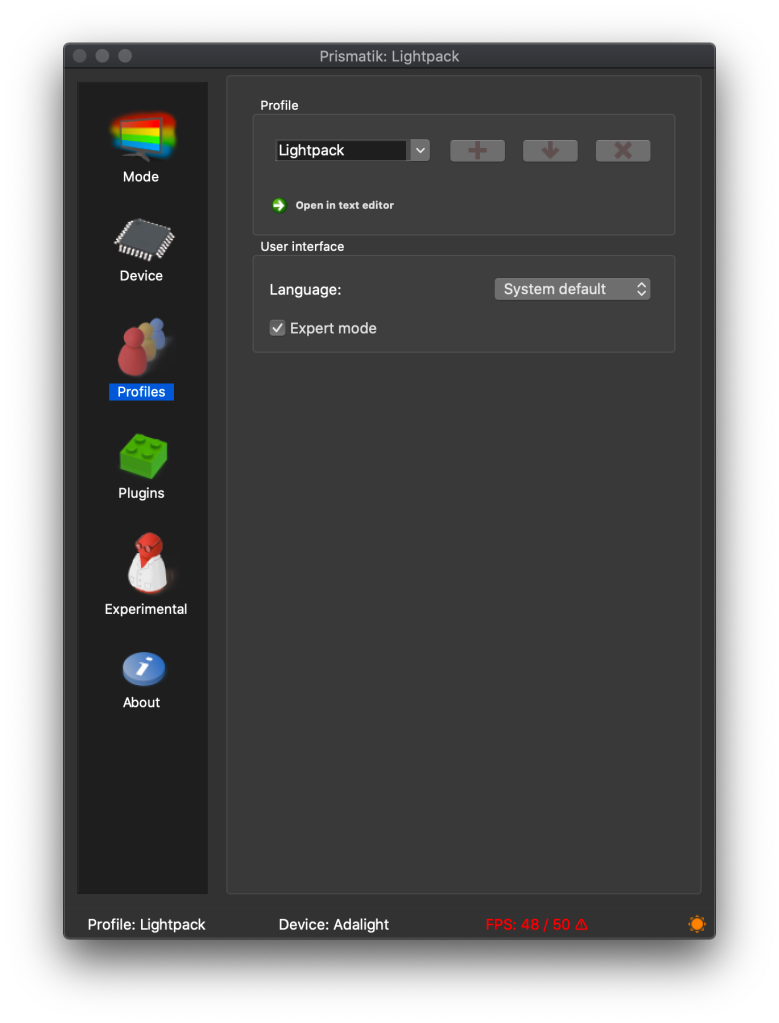
Enable “Expert mode” on the profile section of Prismatik, this will let you fine tune the screen grabber. This is the most important part to get good performance in movies and fast-changing multimedia content.
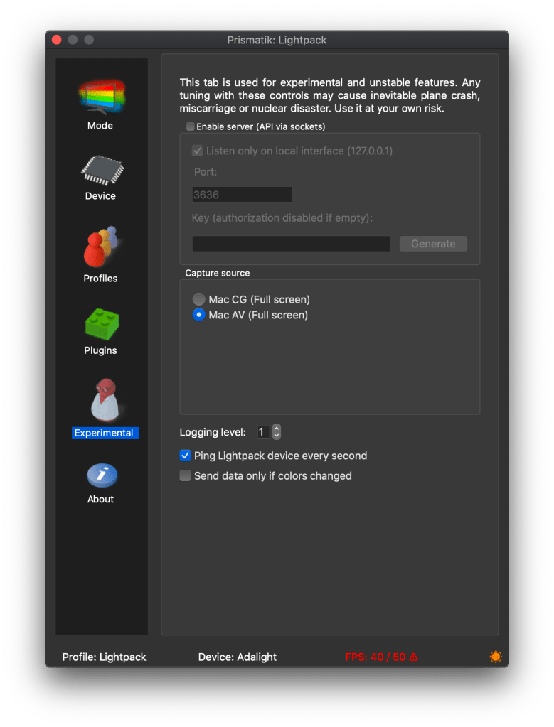
Once Expert mode is enabled you’ll get a new option on the menu, click on Experimental and change the Capture source from Mac CG to Mac AV, this is the most performant screen grabber on newer versions of macOS.
On the “Mode” option you can swap between “Screen grabbing”, “Mood lamp” and “Sound visualization”.
Check “Screen grabbing” and set the Grab interval so something you feel confortable enough for your system. This can be resource intensive if set too low, so find a value that changes LEDs fast enough but doesn’t take too much CPU cycles away from you.
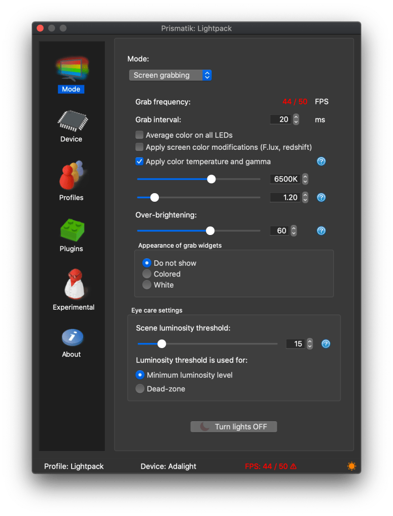
I have it set at 20 fps, and it usually keeps up, depending on my computer load. Prismatik sits at 8% CPU and WindowServer at 6-7%. This is in a single core, since I have a 4,2Ghz i7 it’s not noticeable at all.
Wrapping up
Last thing to do is tidy everything up. Use the double sided tape if your strips doesn’t already come with it or if you’re using the strip holders.
You can also place the microcontroller in a box to avoid desk clutter. I used an enclosure generator written in OpenSCAD and 3D printed a box to keep it all away from view.
If you have any questions don’t hesitate to comment!